Logic Converter
Description
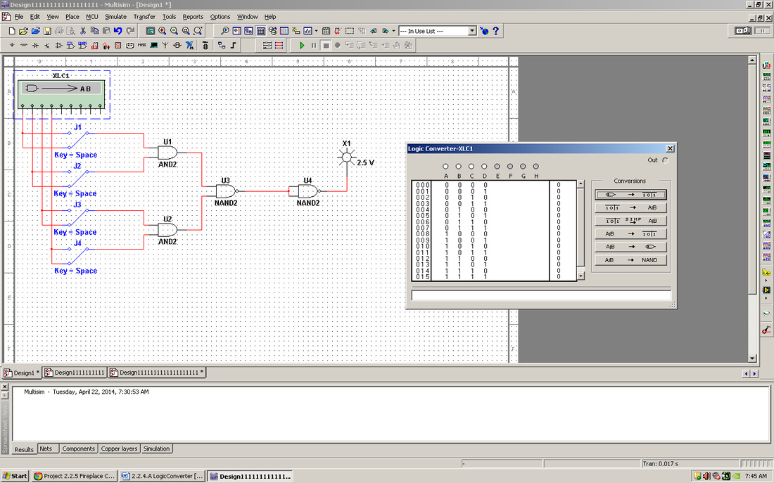
Now that you are all experts at logic simplification using Boolean algebra and K-Mapping and can implement virtually any combinational design using AOI, NAND, and NOR gates, it’s time to let you in on a little secret. A tool located within the Multisim Circuit Design Software, called the Logic Converter, can do much of this work for you. You might be asking yourself why you weren’t given this tool sooner. As an engineer you need to know how to design these types of circuits with and without the aid of such tools. Besides, who do you think designs tools like the Logic Converter? That’s right, an engineer. In this activity you will complete a brief tutorial and use the Logic Converter to create and simulate both an AOI and NAND circuit design.
Conclusion Questions
1. The AOI implementation with the logic converter gave me more clean and accurate result than entering it manually.
2. NAND only implementation gave me nearly all the same results that AOI did. Some values were a little off, though.
3. The only big limitation with the logic converter is that any value below 0.8 is low and any value above 2.0 is considered high. Sadly, any number in between cannot be used.
2. NAND only implementation gave me nearly all the same results that AOI did. Some values were a little off, though.
3. The only big limitation with the logic converter is that any value below 0.8 is low and any value above 2.0 is considered high. Sadly, any number in between cannot be used.
