NAND Logic
Description
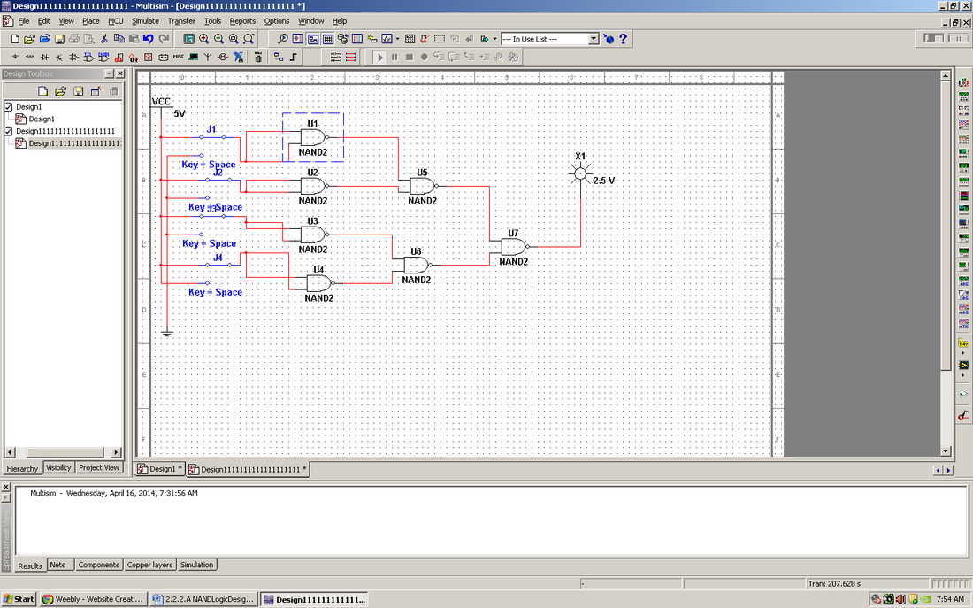
The block diagram shown below represents a voting booth monitoring system. For privacy reasons, a voting booth can only be used if the booth on either side is unoccupied. The monitoring system has four inputs and two outputs. Whenever a voting booth is occupied, the corresponding input (A, B, C, & D) is a (1). The first output, Booth, is a (1) whenever a voting booth is available. The second output, Alarm, is a (1) whenever the privacy rule is violated. In this activity you will implement NAND only combinational logic circuits for the two outputs Booth and Alarm. These NAND only designs will be compared with the original AOI implementations in terms of efficiency and gate/IC utilization. In a future activity, these NAND only designs will be compared to the circuits implemented using only NOR gates.
Conclusion Questions
1. Both of my AOI implements needed two IC chips.
2. For my NAND implement, only one IC chip was required.
3. NAND implements require much less wiring and IC chips than AOI logic.
4. Yes, NAND gates could be used. They would be quite helpful because they would require much less wiring.
2. For my NAND implement, only one IC chip was required.
3. NAND implements require much less wiring and IC chips than AOI logic.
4. Yes, NAND gates could be used. They would be quite helpful because they would require much less wiring.
