Digital Signals
Description
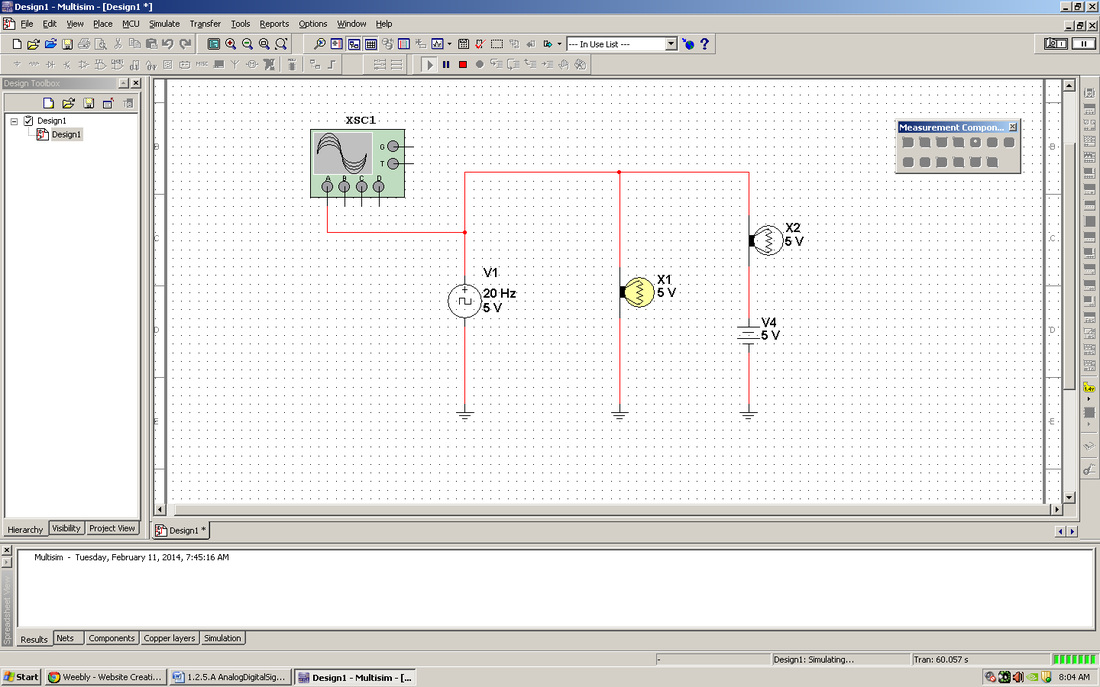
Even though this is a course in digital electronics, it is important to understand that the world around us is analog. Virtually everything that can be designed with digital electronics is used to either control or monitor something in the world around us, and this world is analog. Thus, to be an effective designer of digital electronics, it is important for you to understand the characteristics of both analog and digital signals. In this activity you will examine several analog and digital signals to determine their amplitude, period, and frequency. Additionally, you will gain experience using the oscilloscope within the Circuit Design Software (CDS).
Conclusion Questions
1. Analog and digital signals differ for three reasons. Analog signals are continuous, difficult to use, and have an infinite range. Digital signals are discrete, easy to use, and have a limited (2) range.
2. A: Peak - To - Peak / B: Peak / C: Period.
3. A: Amplitude / B: Time High / C: Period / D: Time Low / E: Rising Edge / F: Falling Edge
4. The two standard acceptable voltage levels in a digital signal are Logic High and Logic Low.
2. A: Peak - To - Peak / B: Peak / C: Period.
3. A: Amplitude / B: Time High / C: Period / D: Time Low / E: Rising Edge / F: Falling Edge
4. The two standard acceptable voltage levels in a digital signal are Logic High and Logic Low.
